
The controls on the 3D viewer change which bodies you see, focus the view on one setup and measure the part. They work the same on every stage. The setup selector and body chips are in the bottom-left corner; Measure and Zoom to fit are in the toolbar at the bottom.
Body chips
There's one chip per type of body in your part: Part, Stock, Workholding (with the number of bodies in the setup you're viewing), Avoidance geometry, Other bodies (bodies that aren't any of the others) and Annotations (PMI, if the part has any). The eye icon on each chip shows whether that type is shown, semi-transparent or hidden.
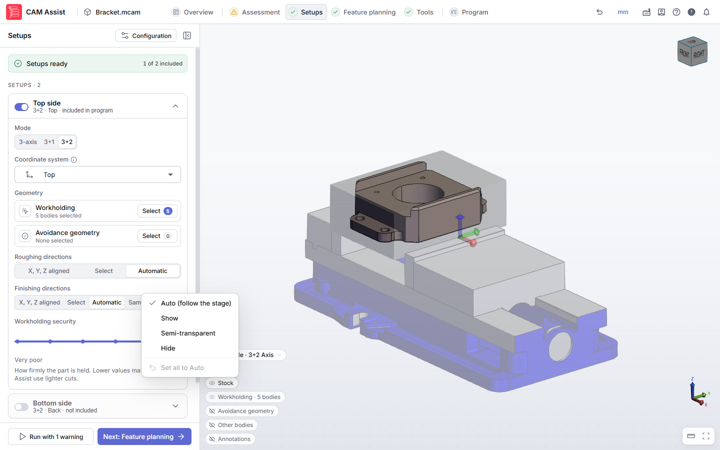
- Click a chip to choose:
- Auto (follow the stage): CAM Assist decides (see below).
- Show: solid.
- Semi-transparent: see-through. Not offered for Annotations.
- Hide: hidden.
- Set all to Auto: puts every chip back to Auto.
- Middle-click a chip to show or hide that type straight away.
A dot on a chip means you set it yourself. When any chip is set by hand, an Auto chip appears at the end; click it to let each stage choose again. CAM Assist remembers your choices on this computer.
What Auto shows
| Stage | Part | Stock | Workholding | Avoidance geometry and other bodies |
|---|---|---|---|---|
| Overview, Assessment, Setups, Program | Solid | Semi-transparent | Semi-transparent | Hidden |
| Feature planning | Solid | Hidden | Semi-transparent | Hidden |
| Tools | Solid | Hidden | Hidden | Hidden |
Setup selector
The pill next to the chips shows All setups, or the setup you're focused on and its machining mode, for example "Top side · 3+2 Axis". Click it and pick a setup to focus the view on it, or Show all. It's greyed out, with the tooltip Setup selection disabled, no setups available., when the part has no setups.
3D, Drawing and Split
When you've added a part drawing, the toolbar shows 3D (model only), Drawing (drawing only) and Split (both). In Split, choose Model above drawing or Model beside drawing, and drag the divider to resize them. The body chips are hidden while the drawing covers the model. See Attach a part drawing to view while you work.
Measure
Click Measure (ruler icon) to open the measure tools. See Measure the part in the 3D view. Click it again (Stop measuring) to close the tools and remove the measurements. Measuring isn't available while you're picking geometry for a setting.
Zoom to fit
Click Zoom to fit to fit the whole part in the view.
SpaceMouse
You can pan, zoom and rotate the 3D view with a 3Dconnexion SpaceMouse. It's off by default.
- Install the 3DxWare driver from 3Dconnexion and make sure it's running.
- Click Account (person icon in the header) > Preferences and turn on SpaceMouse. Connected to the 3Dconnexion SpaceMouse driver. confirms it.
- Close Preferences and click the 3D view. The SpaceMouse moves the view while the 3D view has focus.
If you see "Could not connect to a 3Dconnexion SpaceMouse", see CAM Assist preferences.
Model status messages
| Message | Meaning |
|---|---|
| Waiting for model... / Converting model for visualization... / Loading model... | The 3D model is still loading. Wait for it. |
| Model conversion failed. | CAM Assist couldn't display the model. Close CAM Assist and start it again. If it happens again, check the part model for problems such as gaps; see "Non water-tight model" or "Geometry assessment error" in CAM Assist. |