

The Cutting Parameters Explorer lets you trade cycle time against tool load for one operation and see the effect on feeds, speeds, deflection and other measures before you save. This article covers the explorer you open from an operation in the Program stage.
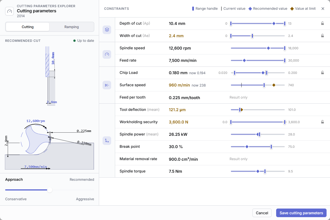
You can also open it from a cutting parameter preset (see Fill a preset from the Cutting Parameters Explorer) and, in Autodesk Fusion and Mastercam, from an operation in your CAM package (see Cutting Parameters Explorer in Autodesk Fusion and Cutting Parameters Explorer in Mastercam).
Open the explorer
- In the Program stage, click the operation's row to open its panel.
- Under Cutting parameters, click Open cutting parameters explorer.
If it's greyed out, hover over it to see why, then see Cutting Parameters Explorer or Edit cutting parameters is greyed out.
Controls
The left side shows the tool and stock material, a diagram of the Recommended cut, and the approach. The status reads Updating while CAM Assist recalculates and Up to date when it's done. The right side lists the Constraints.
| Control | What it does |
|---|---|
| Usage switch | Shown when the operation has more than one usage, for example Cutting and Ramping. Each usage has its own settings. |
| Approach slider, Conservative to Aggressive | Moves all cutting parameters toward lower tool load or shorter cycle time. Ranges from −1 to 1 in steps of 0.1, starting in the middle. The label reads Recommended, or for example More aggressive (30%). The change applies when you let go. |
| Constraint rows | One row per measure, grouped into Engagement, Speeds and feeds, Finish, Chip and cutting speed and Loads and power. Drag the range handles to limit a measure. now shows the operation's current value when it differs from the recommendation. |
| Padlock on a row | Lock value fixes the measure at one value, which you can type. Double-clicking the slider also locks it. Unlock constraints releases it. |
| Reset on a row | Reset constraints puts back the recommended range. Shown only after you change it. |
| Result only rows | Calculated from the other settings. You can't limit them. |
| Legend | Range handle, Current value (the operation's value now), Recommended value and Value at limit (a value pinned against a tool or machine limit). |
| Save cutting parameters | Saves the values to the operation as custom cutting parameters and recalculates the program. |
| Cancel | Closes without changing the operation. Escape and the close button do the same. |
When the save finishes you see Program successfully updated, and the operation's row shows Custom params. If the save fails, you see "An error occurred". See "An error occurred" in CAM Assist.
A warning icon on a row means the operation's current value is outside the range you set. Hover over it for the value and the limits.
Measures you might see
| Measure | Unit |
|---|---|
| Depth of cut (Ap), Width of cut (Ae), Step over, Step down, Stock to leave, Bore diameter, Offset tip to feature | mm |
| Tool approach direction, Ramp angle | degrees |
| Feed rate, Plunge feed rate, Ramp feed rate | mm/min |
| Spindle speed | rpm |
| Surface speed | m/min |
| Feed per tooth | mm/tooth |
| Plunge feed per rev | mm/rev |
| Chip Load | mm |
| Tool deflection (mean), Surface roughness, Maximum geometric cusp size | µm |
| Break point | % |
| Material removal rate | cm³/min |
| Spindle power (mean) | kW |
| Spindle torque | N·m |
| Workholding security | N |
Which rows appear depends on the tool and usage. Units are shown in metric here; the explorer follows your unit setting. See Switch between mm and inches. For what each measure means, see What do the Cutting Parameters Explorer measures mean?
Terms used
- Usage: what the tool is doing in the operation, such as cutting, ramping, finishing or roughing.
- Workholding security: how securely the part is held. See What is workholding security?
- Chip load: the thickness of material each cutting edge removes.